
Page 84 - LIT-18626-12-95
P. 84
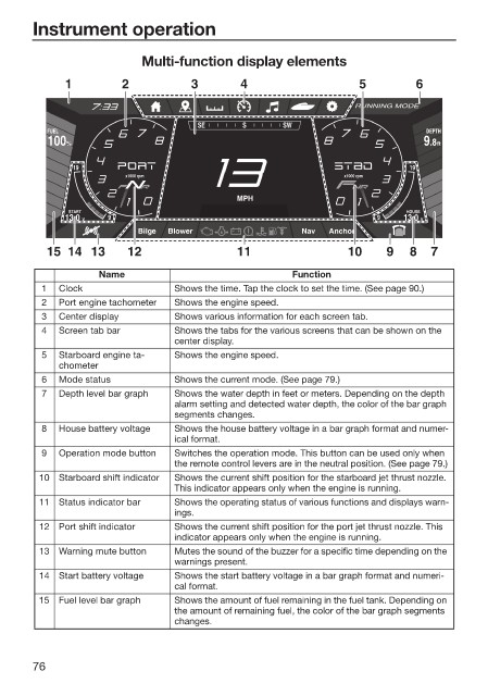
Instrument operation


                         Multi-function display elements
            1         2           3       4                    5        6

                                                              RUNNING MODE
                                   SE      S      SW
         FUEL                                                             DEPTH
         100 %                                                             .8 9  ft

              19                                                       19
                       x1000 rpm                            x1000 rpm
                                          MPH
             START                                                     HOUSE
            13.0  V  9                                            9   13.0  V
                         Bilge  Blower               Nav  Anchor
         15 14 13      12                 11                 10    9   8   7

                  Name                             Function
        1  Clock               Shows the time. Tap the clock to set the time. (See page 90.)
        2  Port engine tachometer  Shows the engine speed.
        3  Center display      Shows various information for each screen tab.
        4  Screen tab bar      Shows the tabs for the various screens that can be shown on the
                               center display.
        5  Starboard engine ta-  Shows the engine speed.
           chometer
        6  Mode status         Shows the current mode. (See page 79.)
        7  Depth level bar graph  Shows the water depth in feet or meters. Depending on the depth
                               alarm setting and detected water depth, the color of the bar graph
                               segments changes.
        8  House battery voltage  Shows the house battery voltage in a bar graph format and numer-
                               ical format.
        9  Operation mode button  Switches the operation mode. This button can be used only when
                               the remote control levers are in the neutral position. (See page 79.)
        10  Starboard shift indicator  Shows the current shift position for the starboard jet thrust nozzle.
                               This indicator appears only when the engine is running.
        11  Status indicator bar  Shows the operating status of various functions and displays warn-
                               ings.
        12  Port shift indicator  Shows the current shift position for the port jet thrust nozzle. This
                               indicator appears only when the engine is running.
        13  Warning mute button  Mutes the sound of the buzzer for a specific time depending on the
                               warnings present.
        14  Start battery voltage  Shows the start battery voltage in a bar graph format and numeri-
                               cal format.
        15  Fuel level bar graph  Shows the amount of fuel remaining in the fuel tank. Depending on
                               the amount of remaining fuel, the color of the bar graph segments
                               changes.


       76