
Page 201 - LIT-18626-12-95
P. 201
Trouble recovery
(4) Move the manual release levers of the
shift motors to the electronic operation
1 position.
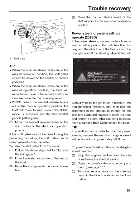
Power steering system will not
operate (252SD)
If the power steering system malfunctions, a
warning will appear on the multi-function dis-
play and the direction of the boat cannot be
changed even if the steering wheel is turned.
1 Shift gate
TIP: S SEE S S S SW W
z When the manual release levers are in the
Check Engine !
manual operation position, the shift gates
Stop steering.
Open service valve of pump. Move cylinder to center NEXT
cannot be moved to the neutral or reverse 0 rpmpm position. Using the two remote control levers, perform the boat x x1000 1000
r
0
steering operation by the engine speed difference.
Consult YAMAHA dealer. QUIT
positions.
z When the manual release levers are in the
manual operation position, the boat will
Bilgee Bl owe Nav Anchor r
o
h
B
N
av
lg
Blowerr
i
A
nc
move forward even if the remote control le-
vers are moved to the reverse position.
z 252SD: When the manual release levers Manually point the jet thrust nozzles in the
are in the manual operation position, the straight-ahead direction, and then use the
boat will move forward even if the DRiVE difference in the amount of throttle for the
mode is activated and the throttle/shift port and starboard engines to steer the boat
paddle (left) is pulled. and return to shore. After returning to shore,
(7) Move the manual release levers of the have a Yamaha Boat Dealer check the boat.
shift motors to the electronic operation TIP:
position. If a malfunction is detected for the power
If the shift gates cannot be raised using the steering system, the maximum engine speed
preceding procedure, the shift gates can be will be limited to approximately 5000 rpm.
raised manually from the water.
To raise the shift gates from the water: To point the jet thrust nozzles in the straight-
(1) Follow the above steps 1–4 for “To raise ahead direction:
the shift gates”. (1) Stop the engines and remove the clip
(2) Enter the water and move to the rear of from the engine shut-off switch.
the boat. (2) Open the driver’s side console compart-
(3) Raise the shift gates to the forward posi- ment. (See page 107.)
tion. (3) Turn the service valve on the steering
pump in the direction shown in the illus-
tration.
193